Bowsprit standing rigging. Ship's rigging What is a ship's bowsprit
- What about dealing with him? Just a tilted log! Xenia said.
– Even with a "simple log" you need to know the names of the parts ... The rear end of the bowsprit is called a spur, like a mast. Front - but about to, like a boom, hafel or ray.
The spur of the bowsprit is fixed between two strong bars (b and teng and m) that go from the deck to the very bottom. In addition, the bowsprit is attracted to the bowsprit by a special bracket, it is called v a ter - v l and n g.
- But he's on top, on the deck, and not near the water, - Slava was surprised. - Why "water ..."?
- The fact is that the front part of the stem, with which it cuts through the water, is called a water cut. The waterwooling is attached to it ... Actually, the word "wooling" means "rope fastening". Because it was with cables in the old days that the bowsprits were fixed on the water cutter ...
You see how much is connected even with a "simple log". But simple, that is, from one tree, bowsprits are found only on small ships. And we are building a complete frigate, with all the details of the spars. Therefore, our bowsprit has two extensions, they are attached to each other with bushsprit and ezelgoftam.
The second part of the bowsprit is called UTL E GAR. And the continuation of the legar is BOM-UTLEGAR.
“It would be more logical to use a bram-fitler,” Slava remarked.
- May be. But it just so happened: "bowsprit, jib, bom-jib".
Bowsprit, jib, bom jib!
What a great way to run on them! -
composed by Anton Shtukin.
“Sometimes the sailors have to go for a run there,” Yakov Platonovich agreed. But it must be done skillfully and carefully. And then not long to be in the water.
“But they’re stretching a net under the bowsprit!” Xenia exclaimed. - Here, on the Meridian model ...
- Yes. But this was not always the case. On the old large sailboats, the bowsprits were huge - whole masts! Try to make a network for such a giant! Yes, even when it bristles with long spars.
- What offshoots? Anton was surprised.
- Sometimes a spar is attached to the bowsprit, which is called BLINDA-RAY. "Blind" in translation into Russian means "blind". In past centuries, a quadrangular sail was tied to the blind yard, which helped with the maneuvering of a heavy ship ... It helped to help, but it was hard to see it from the deck, which is why it was called blind. Abandoned the use of the blind in the eighteenth century. But the rail remained - for stretching the cables that hold the bowsprit from the sides. However, sometimes now, instead of a blind-ray, they put two processes - BLINDA-HAFEL.
And under the bowsprit, approximately in the same place where the blinda-rai or blinda-gafels are attached, another spar part is often placed. Such a process that looks obliquely or vertically down. This is MARTIN Geek. Why "geek" is understandable. It looks like mast booms. And why "Martin", I, to tell the truth, I do not know. Maybe it was invented by a shipbuilder with that name ...
I knew a cadet who liked to compose poems about sails and storms. I remember these lines:
Water and sky met in a noisy dispute,
And the ocean was boiling wild.
And our ship flew forward over the sea,
Ripping out combs with a martin geek...
Antosha Shtukin sighed enviously. He did not yet know how to invent such beautiful poems.
- And at the end of today's classes we will make the last spar drawing, - said Yakov Platonovich. - Bowsprit with all the details. I will try to start, and you, Slava, help ...
And so they did...
- Just a real spreading tree on the ship's bow, - said Vasya.
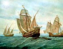
“Yes,” agreed Yakov Platonovich, brushing off the chalk from his palms. - And in the days of Magellan and Francis Drake, on heavy ships like galleons and old ships of the line, an additional mast was put on the bow of a jib or bom-jib - with one or two yards, with a top. That's what it was called - b u shp r and t n a i m a ch t a.
And behind the mizzen on such ships there was sometimes another mast - also a small, auxiliary one. B o n a v e n t ur – ma ch t a. "Bonaventure" in some languages means "good luck". Probably, the sailors believed that this mast would make the management of the ship more successful.
The main parts of the deck and superstructures of a sailing ship (starting from
nose), formed in the sailing fleet:
latrine -
? overhang in the bow of the sailing vessel, on which the bow decoration was installed, and on the sides? latrines for eqi-
page (at present, all toilets on ships and vessels, regardless of location, are called latrines);
tank
-? a superstructure at the fore end of the ship, starting from the bow, which serves to protect the deck from flooding on the opposite
wave, to accommodate office space (painting, skipper's
and etc.). Such a superstructure partially recessed in the ship's hull (usually half the height) is called a forecastle;
waist ? - part of the upper deck from the foremast (first from the bow), or from the bow superstructure to the main mast (second from the bow), or aft superstructure;
quarterdeck (shantsy) ? - aft upper section of the deck, raised by a ledge, where all the controls for the sailing vessel were located;
ut ? - part of the deck between the mizzen mast (the third aft mast) and the aft flagpole.
In the XV? -XVI centuries, a fourth aft mast was also installed on ships, which the British called bonaventure ? mast, and the Italians? fell .
A strongly inclined bow mast is called bowsprit , the angle of its inclination to the horizon is now about 20 °, on ancient ships and galleons about 36 °.
Sails were placed on the masts, which ensured the propulsion of the vessel. Did the sails consist of several sewn panels of special linen fabric? canvases.
Are there two main types of sails? straight and oblique. Straight sails are carried on the yards, slanting -? on the stays (staysails) and on gaffs(trisely).
The edges of the sails, called luffs , for the fortress they are sheathed with a special rope, it was called lyktrosome . Due to the large number of different sails, rigging and gear, there are special names for them, which constitute a kind of maritime specificity and a source of special pride for real sailors.
An idea of the sails of 18th century ships is given in Fig. 9.8, which shows a three-masted ship of the 1st rank with full armament. Such ships carried the following sails.
Straight sails (the names are indicated in the figure by numbers in order from bottom to top):
on bowsprit blind (1) and bowen blind (2); on the foremast? fock (3), fort marseille (4), fort bramsel (5); on the mainmast? mainsail (6), mainsail (7), mainsail (8); on a mizzen mast? - cruise-marseille (9), cruise-bramsel (10). Oblique sails: on a bowsprit? fore or fore staysail (11), fore sten staysail (12), jib (13); between foremast and mainmast? mainsail (only on ships with less than 50 guns), mainsail-staysail (14), midshipsail (15), mainsail-bram-staysail (16), mainsail-bram-staysail; between the main and mizzen masts? mizzen staysail or apse (17), cruise-wall-staysail (18), cruise-bram-staysail (19); on a mizzen mast? mizzen (20).
In favorable weather, in addition to the main direct sails, additional ones were placed to increase speed? - foxes :
on the foremast and mainmast? under- and mars-foxels. By the end of the century, bram-foxels began to be used.
It should be noted that sailing equipment is very diverse, depending on the type of vessel and the period of development of shipbuilding.
The placement of weapons, ballast and provisions on sailing ships was strictly regulated, which was the result of a long test of time.
 The loading of a sailing ship in the 18th century was carried out as follows (Fig. 9.9). In the lower part of the hull, in the so-called water hold, there was a cast-iron ballast. These were cast-iron bars weighing 8 and 2.4 pounds *), which were laid, tightly pressing against each other, from one side to the other. Moreover, in the area of the mainmast, in the center of gravity of the vessel, the largest number of bars was placed. To prevent the ballast from rolling from side to side during pitching, the hold was divided into longitudinal compartments, which were called banks. After the cast-iron ballast was covered with small stone, empty water barrels were placed on it. At the same time, the largest barrels in the bottom row were tightly placed against each other and half buried in stone ballast. After laying the lower layer (log, hence the marine term “stand lag”, i.e. side), the barrels, starting from the middle one, located in the diametrical plane of the vessel, were filled with water from a hose. The average lag of the smaller barrels was placed on the bottom layer.
For sailors to work in the hold above the barrels, a space of about one meter was left. The voids between the barrels were filled with firewood. Provisions (wine, oil, corned beef) were stored in some barrels.
The water accumulating at the bottom of the hold was pumped overboard using pumps installed near the main mast. To protect the pumps from clogging and damage from the very bottom to the lower deck, a special box was built around the mainmast, which was called lyalo or vel.
To accommodate all dry provisions (sacks with flour, salt, cereals) and cook facilities (boilers, plates, cups, scales) under the lower deck for the entire width of the ship at a distance of 1.9 m, a platform was made
(cockpit).
The space under the cockpit (hold) was divided by transverse bulkheads into a number of large compartments: in the central part of the ship? water hold, bow (large) and stern (small) hook chambers.
Kruyt chambers were intended for storing gunpowder in barrels, which were tightly stacked on racks. Gunpowder was poured into caps *) in specially designated places.
Provisions were stored in the captain's and officer's cellars, which were located in front of the aft hook chamber. The bottom of these cellars was covered with sand. They also had special compartments for bombs.
and pomegranate. Artillery accessories and supplies (horns, kokors, leathers and incendiary pipes) were laid out above the kruyt chambers. Skippers' cabins were located near the exit from the hook-chamber. Canvas, awnings, sailing threads, lines, piles, hammers and other ship accessories were also stored here.
Galleries along the sides of the cockpit were used by carpenters and caulkers to seal holes during battles.
For the sick and wounded, the middle part of the cockpit was intended, as a place with the least impact of pitching.
Sailors, gunners and soldiers lived on the lower deck, closer to the bow of the ship. Here were the anchors. In the place where the anchor ropes were drawn in, there was a clubhouse for storing the anchor chain or rope. Cluzback was appointed to prevent water from spreading over the vessel when choosing an anchor, it was well caulked and tarred, and had scuppers for water drainage.
Artillery officers and navigators lived in a cabin behind the main mast. Nearby was the ship's office. Boarding weapons (muskets, pistols, pikes, etc.) were stored nearby. In front of the mizzen mast there was a special place for guns.
For sampling anchors, a large spire was used, which was located between the main and mizzen mast. It had two drums: one on the first and the other on the second battery deck. For lifting heavy
Stey used a small spire, which was located on the upper deck between the fore and main masts.
The captain-lieutenants and lieutenants occupied a wardroom, which was located in the aft part of the ship on the upper deck (operdeke). Midshipmen and midshipmen lived under quarter quarters.
On the quarterdeck there was a ship's compass in a binnacle. On the upper deck between the foremast and the main mast there were rosters? Stands for boats and spare spars. Captain's cabin
relied in the stern of the ship.
The ship's priest lived in a cabin on the starboard side.
 Galley
(kitchen on the ship) was in the bow under the forecastle.
Galley
(kitchen on the ship) was in the bow under the forecastle.
In front of him, on one side, there was a ship's infirmary, and on the other, a wick was attached and a barrel of water was installed.
On the upper deck between the small and large spiers during the voyage there were fences and cages for chickens, ducks, geese, pigs and calves.
On the ships of the slave traders (in the middle part), when taking on board the “live goods”, the upper yards and bram-stengs were lowered onto the deck, which were fixed at a height of 2.5-? 3.0 m. logs. Boards were stuffed onto the resulting frame. So the entire upper deck turned out to be under a lattice with holes of about 30 cm. From above, to protect from the sun, the structure was covered with bamboo mats. Slaves entering the ship could not jump overboard: the part of the deck where they  were, fenced off by a wall of thick wooden boards? "barricade".
Nets were stretched around the entire ship along the sides inside, in which rollers were stored in a folded state -? team personal belongings. During the battle, they protected the personnel from buckshot and enemy bullets.
The placement of artillery on sailing ships of the navies deserves special attention. The heaviest guns were located on the lower deck - gondek, medium-caliber guns - on the upper deck, and the smallest -? on the dowels and the tank. This arrangement was dictated by the desire to better ensure the stability of the vessel.
The guns were mounted on carriages (Fig. 9.10) and together with them they were fastened with thick (5? -8 inches) tarred ropes (trousers) 2.5 times the length of the gun, connected to the side eyelets (rings). Under  gun carriages were crowbars and gunshpugs (wooden levers for changing the sight of guns when firing), but under the guns? banniki (in the form of a ruff? for cleaning the bore), piercers (for sending the charge to the place) and fawns (devices similar to a corkscrew for removing wad residues). Next to the cannon, in rings of thick rope (fenders), which did not allow the cannonballs to roll around the deck, there was a part of the cannonballs. To protect the deck from damage, wooden pillows with recesses were “littered” under the cores. The rest of the cores were placed in the middle of the deck and around the hold hatches. The cores were stored in boxes located in the hold near the main mast.
 Particular attention was paid to the fastening of the guns in a marching manner (Fig. 9.11). This is not surprising, because the mass of guns reached 500 kg. It is easy to imagine what such a mass moving along the deck when the ship was rolling could do. It should be noted that the strong connections of the gun decks were made of large sizes (Fig. 9.12).
Among the design features of sailing ships (their appearance dates back to the 19th century), experts note the replacement of lever steering systems with calderstock to more modern steering wheel (helm). Since then, the steering wheel has become one of the symbols of the maritime profession.
The design of the steering gear with a calderstock and a steering wheel with cable wiring (which is called a steering cable) is shown in fig. 9.13. Sturtrosovaya wiring made it possible to significantly increase the angle of deflection of the rudder blade (up to 15 ° against the previous 5 °), which improved the maneuverability of sailing ships.
It must be said that attention was paid not only to internal structures during the construction of a sailing ship. During the period under review, shipbuilders considered appearance no less important. Each vessel was an individual production facility, and
shipbuilders tried to give it the features of a work of ship art.
Carved sculptural images of religious and mythological content, ornaments and gilding? everything went to the decoration of the ship. Especially a lot of decorations were on the bow and stern. Fig. 1 gives an idea of this kind of decor. 9.14.
In the subsequent period of development of the sailing fleet (the end of the 18th - the first half of the 19th century), the decoration of the ships became more modest; sculptures, bas-reliefs from the stern practically disappear, only the nasal carvings remain. With the advent of metal and steam, shipbuilders completely abandon this kind of hull decoration.
spars- a set of structures made of metal pipes, profiles and sheets installed on the upper deck of the ship and firmly connected to its hull. The spars of the ship include: masts with their armament (topmasts, yardarms, gaffs), shots, flagpole and guisstaff, cargo booms, davits, trapbeams, trawlbeams, etc.Rigging - a set of gear (cables) of all types, securely fastening individual parts of the spars in place and serving to rig and control them. Rigging is divided into running and standing.
The design of the spar and rigging depends on the size and class of the ship, as well as on the purpose of the spar itself with rigging. With the development of navigation and shipbuilding, the purpose and role of the spars with rigging are constantly changing, which entails their constructive changes.
Masts are the main type of ship spars. Large ships, as a rule, have two masts: the foremast (front, i.e., the first from the bow) and the mainmast (the second mast from the bow); small - one foremast. Masts are used for lifting visual signals, placing signal lights, radio and radar antennas, installing cargo arrows, and on sailing ships for lifting, fastening and controlling sails. On warships, masts are also intended to accommodate control posts for the ship and its combat assets.
Masts are installed in the diametrical plane of the ship vertically or with some inclination to the stern. Like all spars, the masts have undergone great changes in their development. Structurally, the masts are made single, tripod, four-legged, as well as in the form of tower-like mast structures. In the general case, the mast consists of strong vertical beams of the set, perceiving all the forces from weight, wind pressure and inertia forces during pitching, and from thin sheathing sheets. Mast set beams (legs) usually pass through the upper deck and are reinforced on the second deck.
Single mast (Fig. 1.26) - a steel pipe (or spar), waterproof at the seams, is installed on small ships, auxiliary and sailing vessels. Single masts are solid and composite. The lower end of the mast (spurs) passes through the upper deck and is attached to the middle deck (platform); on sailing ships - to the keel. The top end of the mast is called the top. To the top of the mast, if it is composite, the lower end of the topmast is attached, which is a continuation of the mast. Depending on which mast it is mounted on, the topmast is called the fore or mainmast, respectively. The topmast ends with a clod (cloth) - a wooden or metal disc, which has pulleys for signal halyards along the edges. On the klotik red and white klotik lanterns are installed. The upper part of the mast with the topmast is held in the center plane of the ship with the help of standing rigging.
Rice. 1.26. Single signal mast:
1,2 - topenants; 3 - klotik fire; 4 - antenna rail; 5 - topmast; 6 - signal rail; 7 - guys; 8 - signal halyards; 9 - steel pipe (or spar)
The tripod mast consists of three steel waterproof tubes. The upper ends are firmly fastened with a horizontal platform of steel sheets, which is called a marshal. The legs of the mast pass through the holes in the upper deck and are attached to the flooring of the middle deck (ship platform) with their lower ends. On the sites located along the entire length of the mast, there are: radio and radar antennas, rangefinders, searchlights, signal and navigation bridges and other control posts.
Masts on modern ships often have the shape shown in Fig. 1.27. The frame of the mast is sheathed with steel sheets on the outside. Such a mast has a large number of horizontal platforms on which radio and radar antennas are placed. To raise flags and signals, the mast has spreaders of different sizes, which act as yardarms.

Rice. 1.27. The mast of a modern ship:
1 - spreaders; 2, 3 - platforms and devices for placing radar antennas; 4 - steel sheathing sheets; 5 - radio antenna
Tower-like mast structures are a developed superstructure with platforms located in several tiers and representing enclosed spaces used for various combat and command posts.
R e and (slats) are metal or wooden in various sizes; fastened to the masts or topmasts in a horizontal position perpendicular to the diametrical plane of the ship. They are intended mainly for raising signals. On them are single-sheave blocks, in which the halyards are based from special braided non-twisting lines. The middle of the ray is called the top; the ends - with the right and left legs, respectively, to the sides of the ship. The legs of the yoke are supported by ray-topenants, the ends of which are attached to the ends of the yoke on the mast or topmast. Masts are armed with two or even three yards. The lower yard on the foremast is called the foremast; on the mainmast - mainsail. The upper yards are respectively called for-mars-yard, grotto-mars-yard.
The gafel is located on the main mast, below the main yard, at an angle to the mast and is held in the diametrical plane by erens backstays, which are attached to the gaff leg and go to the sides. The lower part of the gaff is called the heel, the upper one is called the kick; The gaff head is supported by topenant. A pulley is cut into the gaff nose, through which the halyard passes to raise the Naval flag on a campaign or gaff lights at night.
Flagpole - a metal hollow or wooden rod installed at the stern of a ship and designed to raise the Naval ensign when the ship is at anchor or against the wall. A clot is attached to the upper end of the flagpole (top). The design of the flagpole allows, if necessary, to quickly fill it up on the deck.
The guis rod is installed in the bow of the ship and serves to lift the guis, and at night - anchor light when the ship is anchored. When sailing at night, a box-type fire is lit in the rear of the guisstock to orient the helmsman on the ship, going to the front wake.
Standing rigging(Fig. 1.28) - gear designed to support and fasten the spars in a vertical, horizontal or other position. Standing rigging is not permanently attached and is not passed through blocks; these include: shrouds, stays, backstays, stay-karnak, topenants, strings of yards, etc.

Rice. 1.28. Standing rigging scheme:
1 - stay-karnak; 2 - headstay; 3 - topenants of yards; 4 - ray strings; 5 - guys; 6 - lanyards; 7 - backstay
Bows - gear that strengthens the masts and topmasts so that they do not lean towards the sides. The upper ends of the shrouds are attached to the butts of the yoke on the top of the mast or topmast; the lower ends - through screw lanyards to special rims (shrouds), which are attached to the bulwark, side plating or deck at the sides.
For r - shtag and - tackle located in the diametrical plane of the ship, which do not allow the mast and topmast to tilt towards the stern of the ship.
Backstay - side gear, going from the top of the mast to the side a little behind the mast and holding the mast together with the guys in the center plane of the ship and preventing it from tilting towards the bow of the ship.
Shag - karnak - horizontal tackle, wound up between the masts, which holds the mast and topmast and prevents them from tilting towards the bow (stern) of the ship.
Topenants and strings are used to hang and hold the yards in a position perpendicular to the diametrical plane of the ship.
Standing rigging is always made of rigid steel cable, which has great strength and little flexibility.
Running rigging- gear in motion and intended for servicing and changing the position of parts of the spars, as well as for lifting and lowering cargo, boats, boats, ladders, signals, sails. Running rigging includes: halyards (signal, etc.), fall hoists, hordeni, sloopback stays, shot-brace, chipmunk, quickdraws, sheets and other mobile gear. For running rigging, flexible steel and growth gel cables are used.
Flemish caracca - shrouds
Guys - stretch marks that hold the mast so that it does not fall, which is good.
A. Nekrasov. Adventures of Captain Vrungel
Carrack model from Nuremberg ( Schlusselfelder Schiff), silver, gilding, 1503. The author is presumably Albrecht Dürer Sr.
The design of fastening the shrouds of the mainmast to the hull of the Flemish carrack is unusual. The first few gears are attached directly to the board, the rest - to a wide channel.
The appearance of a wide horizontal line in an engraving believed to date from the wedding of Charles the Bold and Margaret of York in 1468, with a detailed depiction of ufers on it, is rather unusual. The shrouds at that time were fixed mainly on the deck or directly on the sides, and it was impossible to recognize the methods by which they were stuffed in the available images (you can read about the shrouds on the galleys and the terms associated with this process in one of our previous posts). Usually artists limited themselves to some incomprehensible zigzags. One of the first authentically dated (1493) images of a horizontal riverbed is Michael Wolgemuth's engraving "Ulysses and Circe" in the "Nuremberg Chronicle" by Hartmann Schedel.

Woodcut from Schedel's Nuremberg Chronicle ( Schedel"schen Weltchronik), sheet 41 recto
But even on it, a device for stuffing shrouds is just some kind of zigzags around the gear.
The unusual image of the Flemish caracca is supported by the difference in the style of this engraving from the style of other surviving works of the Master WA: the image of the caracca does not correspond in any way to the period of 1468, but rather corresponds to the style of the last works of the Master, falling on the 1485-1490s. The problem can be solved by assuming that the original image, made for the wedding, was redone in later years. If you look again at the enlarged image of the caracca in the area where the shrouds are attached

then you can see the traces of the removed fragment of the image between the cargo port in the side of the karakka and the channel above it. Partially removed detail apparently represented a cargo port, which was located higher and closer to the stern than the port in the final image. Moving the port to a new location can be easily explained. Loading heavy objects through the cargo hatch in the side was often carried out using hoists on the mainsail, which was used as a cargo boom. The wide channel, as depicted in the engraving, located immediately above the old image of the port, made loading through this port impossible. Apparently, the riverbed is a later addition to the engraving, and along with it, changes were made to the location of the cargo port.
Now about the very method of fastening the guys. Let us briefly consider its evolution. The increase in the size of sailing ships and the growth in connection with this of the tension forces of the standing rigging required new ways of stuffing the cables. There are three such methods in total. The first was similar to the method used when stringing musical instruments. The ends of the guys were wound on pegs (like pegs on a violin). The tension of the gear was carried out with the help of lambs attached to these pins, which also looks very much like a tuning technique for stringed instruments. A good illustration of this option can be seen in an engraving by Hans Burkmayr (1511), located in the book of commentaries of a Strasbourg preacher. Geiler von Kaysersberg to Sebastian Brant's poem " ship of fools» .

Thus, in this case, the tension of the cables was carried out using a kind of collar, a small windlass, equipped, as some researchers believe (H. H. Brindly, 1913), with a ratchet mechanism (ratchet with a dog). However, it cannot be ruled out. that the pins were held in position by a conventional friction clutch, which was more natural in that era. It should be noted that no other images of a similar method of tensioning the cables were found, so a hypothesis was put forward that the image resurrects a long-forgotten, perhaps historically first, method.
Another possible way of stuffing the shrouds was the way of spinning the tackle. To understand its essence, consider the cable-stayed cables that existed at that time. In principle, there are two types of twisted cables: left descent and right descent. In 1973, a special international standard ISO 2 was even introduced to designate these two types of cable winding:

The capital Latin letter S denoted the cables of the left descent, and the capital Z denoted the cables of the right. These letters were chosen because the direction of the line in their middle corresponds to the direction of the strand in the corresponding cable. It’s more convenient for us, I think, there will be another rule: if you look along the cable, then for the cable of the left descent, the strand, moving away from the observer, goes in the left direction, and for the right one, respectively, in the right direction. (For connoisseurs of rifled weapons, there is a direct analogy with determining the direction of cutting the barrel: the right one - “left, up, right” (historically it is Russia, the USA, etc.) and the left one (England, France, etc.)) and, as a rule, they were used for the manufacture of shrouds.

If the cable of the right descent (a) is “twisted” counterclockwise (b), then it becomes shorter, the tension of the cable increases, if it is clockwise (c), the cable lengthens. This property of twisted cables was used for stuffing the cables.
A toggle was attached to the lower end of the shroud, which passed through the hole in the board (we already talk about toggles). By rotating the toggle in the desired direction, the cable tension was increased or decreased.
There are images and even models of sailing ships with a similar way of stuffing the shrouds. For example, in the illuminated Psalters of Luttrell(1320-1340) the miniature for Psalm 89 just shows shrouds with toggles.

Luttrell Psalter (British Library), miniature fragment for Psalm 89
And of course, a wonderful silver carrack model from Nuremberg, a photo of which is given at the beginning of the post, and an enlarged image is given below.

Kohlhausen (H. Kohlhausen. Nürnberger Goldschmiedekunst des Mittelalters undder Durerzeit 1240 bis 1540, Berlin, 1968) suggests that the possible author of the model, Albrecht Dürer Sr., took as a model for it an engraving of the Flemish caracca by Master WA. However, there is one obstacle: on the Dürer model, the method of fastening the shrouds with the help of toggles is used, and on the Flemish karakka, as we have seen, lufers and a channel are used.
And, finally, consider the third way to tension the cables - using blocks. Initially, the guys were stuffed using a single-pulley block, which, as you know, gives a twofold gain in strength. Further improvement of this method led to the replacement of a simple block with a pair of lufers - pulleyless blocks with three through holes in the cheeks, located in the form of a triangle, through which the lanyard lopars are passed (see the above enlarged image of the Flemish karakka in the shroud area). The new design theoretically made it possible to achieve a fivefold gain in strength.

Historically, the introduction of the lufers coincided in time with the introduction of the channels for their fastening: increasing the tension of the shrouds in the new method of their fastening threatened to tear off the side plating, so the blocks were no longer fastened overboard, but on a special horizontal board - the ruslen. Initially, this board was attached to the board with a face, vertically. We see this method of fastening, for example, on a karakk from the painting by Hans Memling "The Seven Joys of Mary"

Hans Memling, The Seven Joys of Mary (1480). Old Munich Pinakothek
The artist depicted eighteen different episodes from the life of Mary and Christ within one huge board. We are interested in the scene in the background depicting the loading of the Magi and their horses onto the ships (on the way back from the Holy Land after the worship of Christ).
The resolution of the available reproductions from this picture is not enough to see the ships on the horizon in detail. Therefore, we give an illustration from the article by A. W. Sleeswyk The Carrack of Hans Memling (1987)

Caracci of the Magi (1480)
Although in this image we do not particularly distinguish the details of interest to us, it is proposed to take a word that on the left ship the shrouds are fastened through the yufers, which are fixed on the board, with its plane pressed against the ship's boron.
We will continue this topic next time.
Majestically dissecting the sea waves - a truly bewitching sight. Now you can see it with your own eyes, except perhaps at the parade of sailing ships in Amsterdam, which takes place every five years. Several centuries ago, watching a sailboat was a common thing among coastal residents. The more massive the ship, the more sails are needed for its fast and smooth running. The sailboat has a complex structure, and each mast on it has its own purpose. You can consider the structure of a sailing ship from its most advanced detail.
Bar at the forefront of a sailboat
In a literal translation from Dutch, a bowsprit is an "inclined pole". The design is a bow beam of a sailing ship that is carried forward. In other words, a bowsprit is a spar, which is a continuation of the bow of the ship and protrudes beyond the stem. It plays the role of a front mast and is installed obliquely at an angle of 30-36 degrees. Initially, it consisted of one section. Subsequently, on large ships, it became composite: as its continuation, a jib was installed, followed by a bom-jib. Like any mast, the rear base of the bowsprit is called a spur. The front end is called a nok, like a boom, hafel or ray.
Design purpose
The main purpose of the bowsprit is to carry forward the front oblique triangular sails - jibs. Due to this design, the sailing area of the ship is increased, which contributes to better handling and higher maneuverability. In addition, the bowsprit is partly used to secure the foremast. Its functions do not end there, because. it is also necessary for securing and raising the bow anchor. Thus, the ship's bowsprit is a multifunctional mast of a water craft.
Front mast dimensions
For ships of different profiles, the length of the bowsprit was different. As a rule, on merchant ships, the length of the forward mast was equal to three-fifths of the length of the mainmast. On ships intended for naval combat, its length was equal to eight-ninths of the length of the foremast. In diameter, the bow beam was comparable to the diameters of the fore and main masts of medium size. At the same time, the thickness of the bowsprit decreased from the base to the toe by almost a factor of two.

Sometimes the bow of the ship was decorated with a latrine (or bow) figure, which was usually located above the bowsprit and depicted, most often, a mermaid, an attractive girl or a lion's head. It is noteworthy that on the other side, on the same overhang, there were restrooms for the crew.